FRC belt calculator
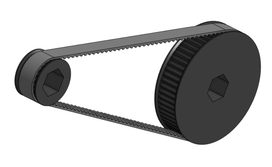
The FRC belt calculator feature allows users to quickly add belt and pulley assemblies to a part studio. Belts may be either GT2 or HTD, and configurable 3D printable pulleys may also be added.
The FRC belt calculator FeatureScript can be found here: FRC belt calculator document
Steps for creating belt runs
Create an FRC belt calculator feature by selecting it from your FeatureScript dropdown.
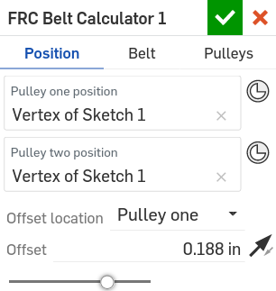
In the Position tab:
Specify a Pulley one position and a Pulley two position to use.
If desired, specify an Offset location (Center, Pulley one, or Pulley two) and a Offset for your belt run, and use
 to reverse the direction of the Offset.
- ..note ::
If you set the Offset location to Pulley one or Pulley two before adding a corresponding Custom pulley in the Pulleys tab, the Offset will be applied from the middle of the belt run.
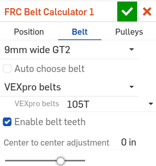
In the Belt tab:
Specify your desired belt standard (9mm wide GT2, 9mm wide HTD, or 15mm wide HTD).
Choose whether you’d like to automatically choose the belt size (Auto choose belt) based on the computed center to center distance (as determined by the distance between your desired Pulley positions, the teeth of Pulley one and Pulley two, and the Center to center adjustment).
Specify a supplier inventory you’d like the belt to be chosen from, or choose Any belt size to choose from any available tooth count.
If you’ve chosen to size the belt manually, enter the desired number of Belt teeth.
Choose whether to Enable belt teeth in order to also create an approximate tooth representation.
If desired, specify a Center to center adjustment to modify the standard belt center to center distance.
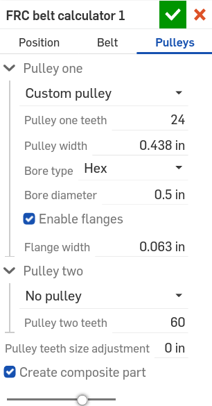
In the Pulleys tab:
Specify the configurations of Pulley one and Pulley two:
Specify whether you’d like to create a 3D printable Custom pulley or No pulley.
Enter the number of Pulley teeth.
If you’ve chosen Custom pulley, specify:
The Pulley width
The Bore type (Hex, Circular, VEXpro spline, or None)
The Bore diameter
Whether to Enable flanges
The Flange width (if flanges are enabled)
The Pulley teeth size adjustment
Choose whether to create the belt run as a single composite part (Create composite part).
Note
Creating a belt run as a single composite part can help simplfy the assembly process later on.
Click
 .
.
Center distance checks
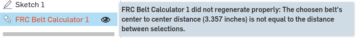
When both pulley positions are defined in the Position tab, the FRC belt calculator FeatureScript will automatically measure the distance between the selected positions and report a warning if the distance between the belts does not match the center to center distance of the belt run.
Note
The belt center to center distance is determined by the number of Belt teeth, the teeth of Pulley one and Pulley two, and the Center to center adjustment.
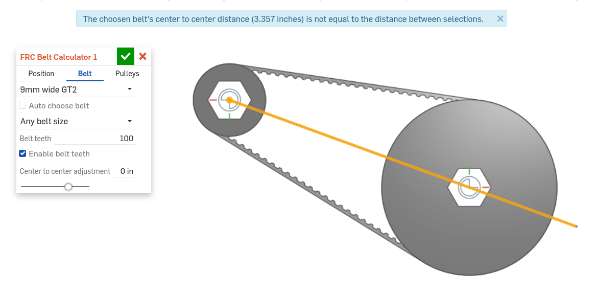
To correct a belt center to center distance error, change the distance between your Pulley one position and Pulley two position selections to match the value displayed in the error tooltip.
Tip
The error tooltip can be seen at the top of the screen while the FRC belt calculator feature is being edited, or by mousing over a broken FRC belt calculator feature in the feature tree.